Pictures by Matthias Domin
Attention: This is on your own risk!
Don't blame me if anything goes wrong!
If you're not experienced in soldering, stop here!
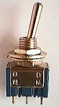
You need:
 - an EPROM type 27c010 or 27c1001 (this is 128K x 8)
 - a 32pin socket
 - a switch ( on-on )
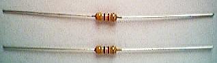
- two 4k7 resistors (1/4W) Colour-code: 1. ring Yellow, 2. ring Purple, 3. ring Red (may be Black)
 - some wire
 - good nerves
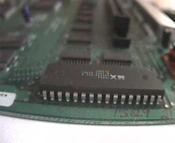
1) Open your Jaguar console and remove the shield. Localize the Boot-ROM,
it's near the power-plugin:
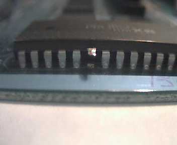
2) Cut /CE (pin 22) as close as possible to the PCB and bend it up:
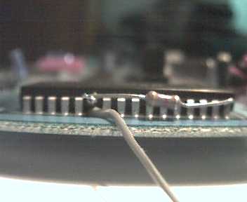
3) Solder a resistor at this pin and at pin 32 (Vcc), this pulls /CE
up:
4) Bend up the socket's pin 22:
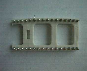
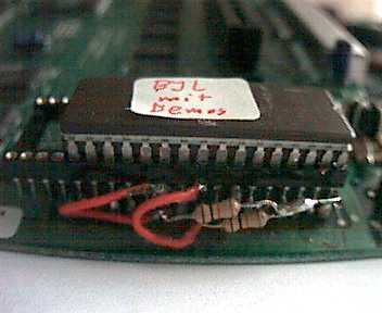
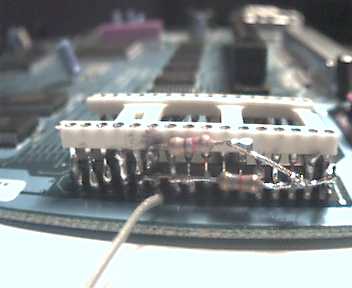
5) Solder the socket onto the original ROM:
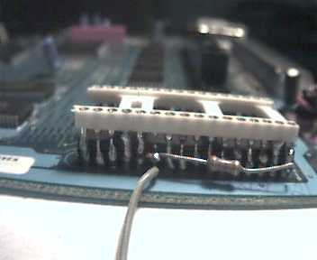
6) Solder the second resistor at pin 22 of the socket and at pin 32
of the ROM:
7) Solder 3 wires to the switch, the main (which is switched) to the /CE on the PCB (don't make a short cut !) and the other two either to pin 22 of the ROM and the socket.
8) Switch you Jaguar ON to test. In one position nothing should happen, in the other, it should boot normally.
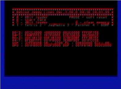
Normal boot-screen:

9) If nothing happens, check all steps and check for short-cuts.
10) Burn the image DEBJAG.IMG at the very beginning of the ROM.
11) Insert your EPROM and switch your Jaggy on.
12) Everything is fine, if a message screen appears, with a 68k register-dump
and a blue or red border:
13) Placing the switch
Don't forget to use some tape on the metall casing where you route
the wires out of it!
Alternative A: Near the power plug.
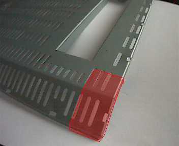
Step A.1
To be able to fix the switch you have now to cut a rectangle out of
the metall-cage cover near the power plug:
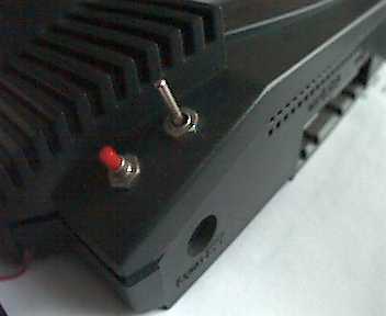
Step A.2
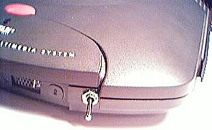
Now drill a hole for the switch into the console cover near to the
power plug. Here is a picture of a Jaguar with an additional reset
key (the red one):
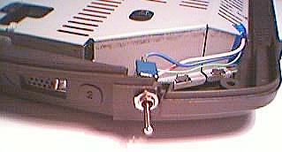
Alternative B: Near the joypad port 2
Step B.1
Drill a hole for the switch into the bottom console casing near to
joypad port 2.
Using alternative B you don't have to work on the metall casing of
the PCB.
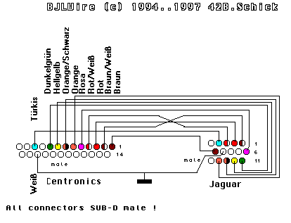
14) Prepare the cable and enjoy hacking the Jaguar. Here's a diagram
of the cable connections (looking at the soldering side):
15) Again, don't blame me, if some errors occur!
Picture of Matthias Domin's Jag. This one has no switch (you can start
any game (cartridge- or CD-based) by pressing fire-button B in the BJL-screen)
and both /CE and /OE are lead to the BJL-EPROM-socket: