
A look at the top of a Atari Lynx model I:
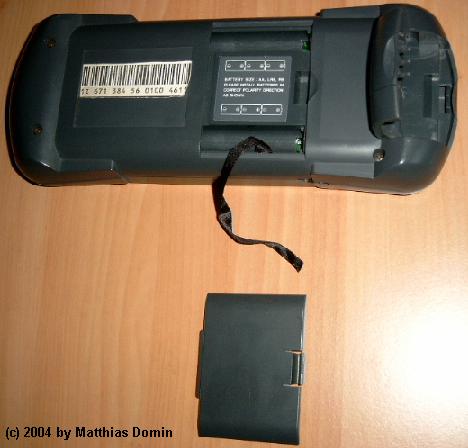
And now at the back of the Lynx I. Both the battery bay and the cartridge bay are openened.
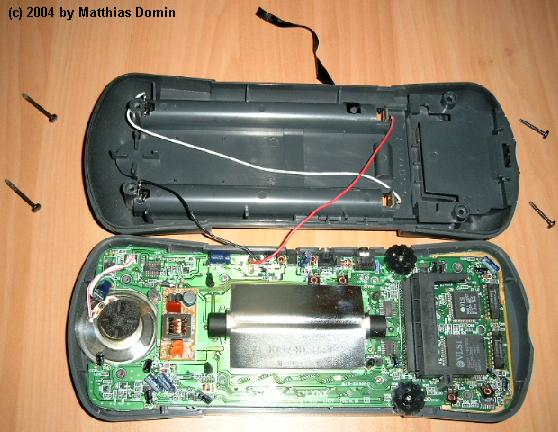
After removing four screws you can easily open the Lynx I.
But please be carefully because the two wires (black and red) coming from the battery bay are soldered to the PCB!
The two custom chips Mikey (68 pin PLCC) and Suzy (44 pin PLCC) are placed at the right of the the cartdrige slot.
Right of them at the edge of the PCB the two 4bit RAM-chips (TMM41464CP-12, 18 pin DIP) are placed.
Between the slot and the screen-light the HC4040 and 74HC164 logic chips are placed. These are used to drive the address-bus of the cartridge slot.
My Lynx I has a C104193-001 REV. B PCB.
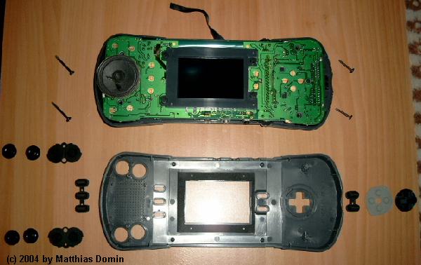
The next picture shows the top of the PCB with the LCD screen and all button parts took apart.
Parts list
top shell: C104175 REV 1
rear shell: C104177 REV 1
cartridge bay doorlid: C104179 REV 1
PCB: C104193-001 REV. B
backlight rear shell: C103746 REV 1