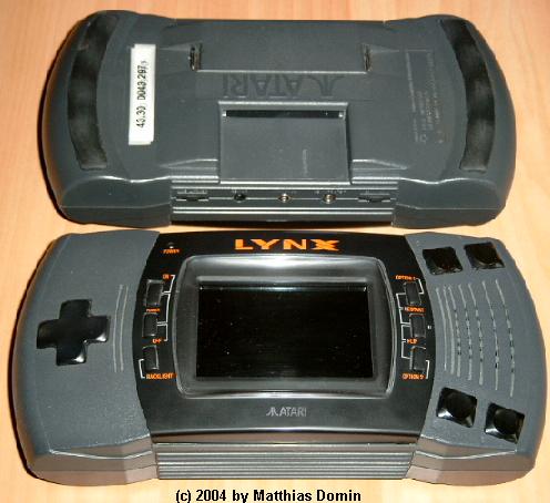
A look at the top and the bottom of a Atari Lynx model II (PAG-0400):
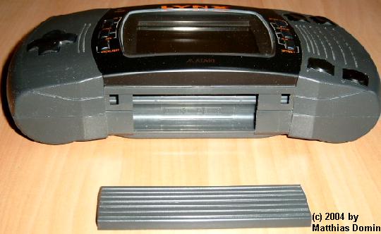
To open the Lynx II remove the battery bay door:
Then find the 4 screws beneath the two ribbon stripes on the Lynx II's rear:
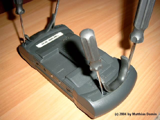
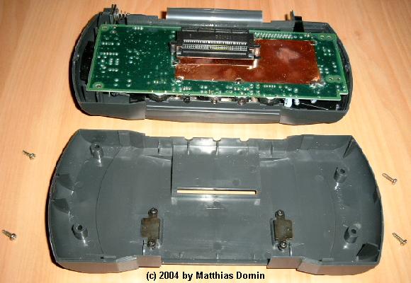
After removing the four screws you can easily remove the rear shell from the rest of the Lynx II.
Turn the Lynx around to look at the battery bay:

Remove the single screw which fixes the wall of the battery bay to the top shell of the Lynx II.
Then remove the batterybay-wall carefully from rest of the Lynx II. You'll need to lift the PCB slightly to be able to do this.
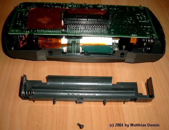
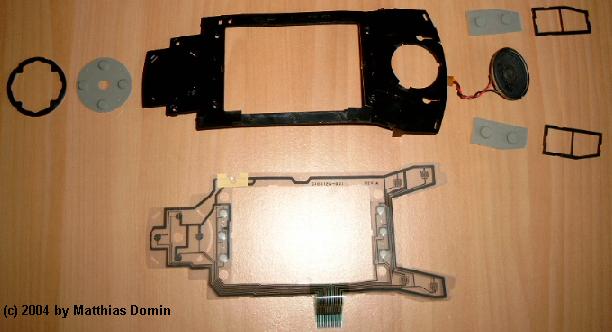
At that time you will have noticed that the PCB is connected with four "cables" to the top shell of the Lynx II:
On the left is the loudspeaker cable (orange connector with two wires).
Next to it is the foil-connector for the LCD-screen
and then comes the foil-connector for the buttons.
On the right is the power cable for the LCD-screen and the backlight (orange connector with two wires, but 3 connectors).
Opening the orange connectors is quite easy, but to be able to remove the two foils from the foil-connectors you need to open the foil-connectors. This is done by pulling on the wings of these foil-connectors.
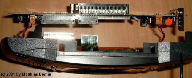
Now you can remove the PCB from the top shell:
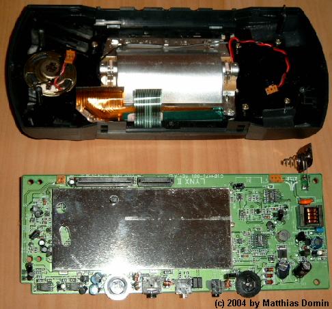
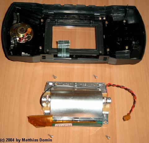
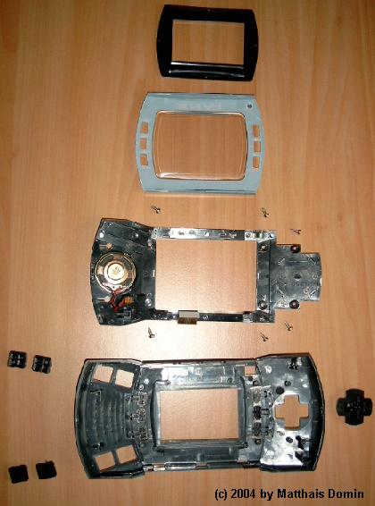
The screen and the backlight unit can be dettached from the top shell after removing 4 screws:
The next two pictures show the main removable parts of the top shell:
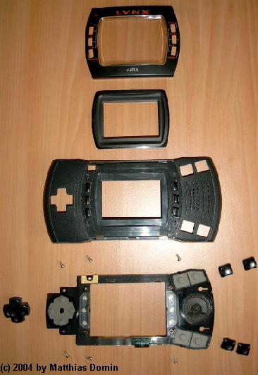
And these are the parts of the button-frame of the Lynx II:
The next picture shows the top of the PCB. As you can see the chip-area is covered with a metal RF-shielding.
On the left lower corner you can see the battery bay-connector.
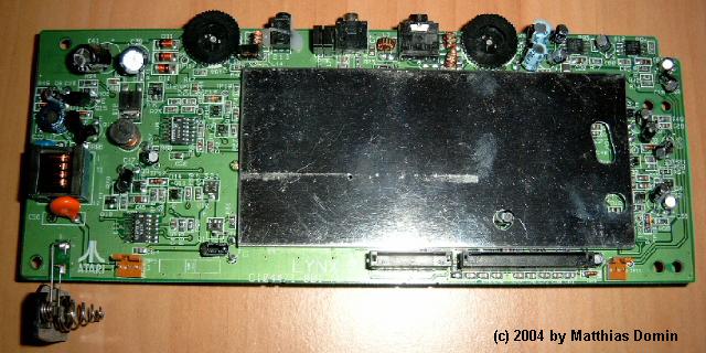
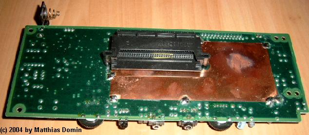
The next picture shows the bottom of the PCB. In the middle is the cartridge slot and a metal RF-shielding is also visible.
On the left upper corner you can see the battery bay-connector.
Parts list PAG-0400
Top shell: C104132 REV
Rear shell: C10413 REV (only five digits!)
Button foil (with power LED): C104126-001 REV. A
Button foil and loudspeaker frame: C104150 REV 2
PCB: C104471-001 REV. A
Backlight rear shell: C104159 REV
Backlight top frame: C104160 REV A
LCD foil: UC-351 20121131 Made in Japan
Slot: C101985-002 2
Battery wall: C104140 REV
The two pairs of fire buttons are labelled "A","B","C" and "D" to find their correct position.
The flat foil for the LCD has 26 signal lines.
The flat foil for the buttons has 14 signal lines.
The loudspeaker has 16 Ohm and 0.2 Watt.
Parts list PAG-0401
Top shell: C104132 REV
Rear shell: C10413 REV (only five digits!)
Button foil (with power LED): C104126-001 REV. A
Button foil and loudspeaker frame: C104150 REV 1
PCB: C104471-001 REV. A
Backlight rear shell: C104159 REV
Backlight top frame: C104160 REV A
LCD foil: UC-351 20044491 Made in Japan
Slot: C101985-001 4 and C101985-002 1 in another device
Battery wall: C104140 REV
The two pairs of fire buttons are labelled "A","B","C" and "D" to find their correct position.
The flat foil for the LCD has 26 signal lines.
The flat foil for the buttons has 14 signal lines.
The loudspeaker has 16 Ohm and 0.2 Watt.